
identify components on a circuit board
Identifying components on a circuit board is a crucial skill for engineers, technicians, and hobbyists working with electronics. Whether you’re troubleshooting a malfunctioning device, designing a new project, or learning about electronics, recognizing the various components on a circuit board is essential. Here are some fundamental methods and tips for effectively identifying components on a circuit board.
The first step in identifying components on a circuit board is to familiarize yourself with the standard symbols and labels used in schematics. Most circuit boards will have a silkscreen layer that displays component designators, such as R for resistors, C for capacitors, Q for transistors, and U for integrated circuits (ICs). These designators help quickly locate and reference components. Additionally, it is important to understand common component symbols to relate them back to their physical forms on the board.
In many cases, circuit board are accompanied by a Bill of Materials (BOM), which lists all the components used, along with their specifications and designators. The BOM serves as a valuable reference for identifying components, as it provides detailed information about each part, including its function, value, and package type. By cross-referencing the BOM with the circuit board layout, you can quickly locate and identify components based on their designators.
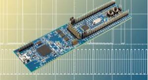
How do you identify components on a circuit board?
A hands-on approach is often the most effective way to identify components on a circuit board. Carefully inspecting the board can reveal various components and their layouts. Look for physical characteristics such as size, shape, color, and markings on components. For instance, resistors often have color bands indicating their resistance value, while capacitors may have labels specifying their capacitance. Integrated circuits typically feature a part number printed on their surface, which can be referenced online or in datasheets to identify their function and specifications.
For components that may not be easily identifiable through visual inspection alone, using a multimeter can provide helpful insights. A multimeter can measure resistance, capacitance, and continuity, allowing you to test components in-circuit or out-of-circuit. For example, measuring resistance across a resistor will help confirm its value, while testing a capacitor for capacitance will indicate whether it is functioning properly. By testing components, you can also identify faulty parts that may need replacement.
Many circuit boards will have a reference layout indicating the position and designators of components. This layout can often be found in the product documentation or design files. By examining the layout, you can identify where specific components are located on the board, making it easier to trace connections and understand the circuit’s functionality. This is particularly useful for complex boards with numerous components.
Components often have manufacturer logos or part numbers printed on them. These markings can be used to look up datasheets and technical specifications online. Searching for these numbers can provide detailed information about the component’s specifications, pin configuration, and electrical characteristics. This is particularly useful for integrated circuits and specialized components, as it can help you understand how they operate within the circuit.