
Signal Integrity on Rigid Flex Printed Circuit Boards
Rigid flex printed circuit boards provide a high level of flexibility and functionality to electronic devices, allowing them to fold and twist into any shape the design requires. They are also great options when space constraints and thickness limitations need to be managed. This is especially true when the product will be used in a rugged, handheld environment like the military, industrial robotics and medical imaging equipment.
A rigid-flex printed circuit board design can be a complex undertaking, especially as the board is designed in three dimensions. The layers are stacked in a unique way and the configuration of the components must be carefully considered to ensure signal integrity and maintain a minimum footprint. Choosing the right materials for rigid and flexible sections, layer count, and copper thickness are all key in making a successful rigid-flex PCB.
When a rigid-flex PCB is used in high-vibration environments, it must be constructed from a material that offers both rigidity and flexibility. This helps to prevent mechanical stress and failure in the flex area. It’s also important to route traces and vias away from the bending regions of the flex circuit. These areas are sensitive and can cause mechanical reliability issues if they’re not properly handled.
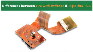
How to Improve Signal Integrity on Rigid Flex Printed Circuit Boards
As a result of their three-dimensional structure, testing and inspection of rigid-flex PCBs is more challenging than for traditional rigid PCBs. Specialized testing equipment and procedures may need to be utilized.
The most critical aspect of a rigid-flex PCB is its ability to withstand the vibration conditions it will be subjected to during operation. This can lead to the occurrence of impedance mismatching and loss of signal integrity, which is why it’s crucial that the PCB be designed with proper materials, layout, and configuration.
A rigid flex circuit board can be more expensive to produce than a conventional rigid board, due to the materials and fabrication processes that go into its construction. This is why it’s important to work with a reputable manufacturer that will provide you with a high-quality, cost-effective solution.
The best way to prepare a rigid-flex PCB for manufacturing is by using a powerful and user-friendly CAD program like Altium Designer. Its integrated MCAD and ECAD tools give you a clear view of your bending region, and it’s easier to create the right packaging for your device.
One of the primary advantages of rigid-flex PCBs is their ability to reduce overall weight and size in electronic devices. Traditional designs using separate rigid and flexible PCBs often require additional connectors and cables to join them, which increases weight, bulk, and the risk of failure. By eliminating these components, rigid-flex PCBs streamline the design and improve reliability.
Rigid flex circuit boards are ideal for use in rugged, handheld electronics. They help to improve the overall durability of your electronic device while providing a degree of flexibility and functionality that is not possible with traditional rigid circuit boards. By following the tips listed above, you can design and fabricate a rigid-flex circuit board that meets all of your requirements.